High-density plasma (HDP) etching systems are pivotal in the semiconductor industry, enabling the fabrication of intricate micro- and nanoscale features critical for modern integrated circuits (ICs) and microelectromechanical systems (MEMS). The characterization of etch profiles in these systems involves a systematic study of the physical and chemical interactions between the plasma and the substrate, which determine the shape, uniformity, and quality of etched features. This article provides a comprehensive exploration of the principles, methodologies, and challenges associated with characterizing etch profiles in HDP etching systems, emphasizing the interplay of plasma parameters, equipment design, and material properties.
Introduction to High-Density Plasma Etching
Plasma etching is a cornerstone of semiconductor manufacturing, utilizing ionized gas (plasma) to remove material from a substrate with high precision. Unlike traditional wet etching, which relies on chemical solutions, plasma etching offers superior anisotropy, enabling the creation of vertical sidewalls and high-aspect-ratio features. High-density plasma etching systems, such as inductively coupled plasma (ICP) and electron cyclotron resonance (ECR) systems, generate plasmas with electron densities exceeding 10^11 cm⁻³, significantly higher than conventional reactive ion etching (RIE) systems. This high density enhances etch rates and allows for finer control over etch profiles, making HDP systems indispensable for advanced nodes in semiconductor fabrication.
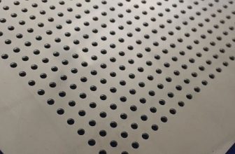
The etch profile, defined as the cross-sectional shape of an etched feature, is influenced by multiple factors, including plasma chemistry, ion energy, gas flow, chamber pressure, and substrate temperature. Characterizing these profiles involves measuring parameters such as sidewall angle, etch depth, uniformity, and surface roughness, often using advanced diagnostic tools like scanning electron microscopy (SEM), atomic force microscopy (AFM), and optical emission spectroscopy (OES). Understanding these characteristics is essential for optimizing process performance, ensuring reproducibility, and minimizing defects in high-volume manufacturing (HVM).
Fundamentals of Plasma Etching
Plasma Generation and Properties
Plasma, often referred to as the fourth state of matter, is a partially ionized gas containing electrons, ions, neutral atoms, and reactive radicals. In HDP systems, plasma is generated by applying a high-frequency electric field, typically at 13.56 MHz, to a process gas mixture. Common configurations include:
- Inductively Coupled Plasma (ICP): Utilizes a radio-frequency (RF) coil to induce a magnetic field, ionizing the gas and creating a high-density plasma. ICP systems operate at low pressures (1–10 mTorr), promoting anisotropic etching.
- Electron Cyclotron Resonance (ECR): Employs microwave energy (2.45 GHz) and a magnetic field to achieve resonance, producing plasmas with electron densities up to 10^12 cm⁻³. ECR systems excel in low-pressure, high-precision etching.
- Capacitively Coupled Plasma (CCP): Generates plasma via parallel-plate electrodes, often used in pulsed modes to control ion energy and reduce micro-trenching.
The plasma’s properties, such as electron density, ion flux, and electron temperature, dictate its etching behavior. High-density plasmas are characterized by a high ion flux and low ion energy, enabling rapid material removal with minimal substrate damage.
Etching Mechanisms
Plasma etching involves three primary mechanisms:
- Chemical Etching: Reactive species (e.g., fluorine or chlorine radicals) chemically react with the substrate, forming volatile byproducts that are evacuated from the chamber. For example, silicon etching with CF₄ produces SiF₄, a volatile compound.
- Physical Etching (Ion Bombardment): Energetic ions physically sputter material from the substrate, enhancing anisotropy by preferentially removing material in the direction of ion incidence.
- Synergistic Etching: A combination of chemical and physical etching, where ion bombardment activates the surface, facilitating chemical reactions. This synergy is critical for achieving high etch rates and vertical profiles.
The balance between these mechanisms determines the etch profile. For instance, chemical etching tends to be isotropic, while ion-driven etching promotes anisotropy, resulting in straighter sidewalls.
Key Parameters Affecting Etch Profiles
Several process parameters influence the etch profile in HDP systems:
- Gas Chemistry: The choice of etching gases (e.g., SF₆, Cl₂, CF₄) and additives (e.g., O₂, Ar) affects the concentration of reactive species and the formation of passivation layers.
- Chamber Pressure: Lower pressures (5–10 mTorr) enhance ion directionality, improving anisotropy, while higher pressures increase the density of reactive species, boosting etch rates.
- RF Power: Source power controls plasma density, while bias power regulates ion energy. Higher source power increases ion flux, and higher bias power enhances ion bombardment.
- Substrate Temperature: Temperature influences the volatility of etch byproducts and the deposition of passivation layers. Cryogenic etching (e.g., at -100°C) suppresses sidewall etching, improving profile control.
- Gas Flow Rate: Affects the residence time of reactive species, impacting etch uniformity and selectivity.
These parameters are interdependent, requiring careful optimization to achieve desired etch profiles.
Characterization Techniques for Etch Profiles
Accurate characterization of etch profiles is essential for process development and quality control. The following techniques are widely used in HDP etching studies:
Scanning Electron Microscopy (SEM)
SEM provides high-resolution images of etched features, allowing measurement of sidewall angles, etch depth, and feature dimensions. Cross-sectional SEM is particularly useful for assessing profile anisotropy and detecting defects like micro-trenching or bowing. For example, SEM analysis of SiO₂ etching in pulsed CCP systems has revealed the elimination of micro-trenching with increased power off-time due to reduced ion bombardment during off-cycles.
Atomic Force Microscopy (AFM)
AFM measures surface roughness and topography at the nanoscale, critical for evaluating the smoothness of etched surfaces. In high-aspect-ratio etching, AFM has shown root mean square (RMS) roughness values as low as 1.77 nm for SiO₂ cavities, indicating high surface quality.
Optical Emission Spectroscopy (OES)
OES monitors plasma chemistry by analyzing the emission spectra of excited species. It is used for endpoint detection and fault diagnostics, though its effectiveness diminishes in deep submicrometer etching. In HDP systems, OES is often combined with interferometry endpoint (IEP) detection to enhance process control.
Interferometry Endpoint Detection (IEP)
IEP uses laser interferometry to monitor etch depth by detecting changes in reflected light intensity. In ICP systems, IEP fringe count algorithms predict the endpoint, enabling precise control of over-etching steps. This technique is particularly effective for thin gate oxide etching, where OES alone is insufficient.
Langmuir Probe Measurements
Langmuir probes measure plasma parameters such as electron density, ion flux, and plasma potential. These measurements correlate with etch rates and profile characteristics, providing insights into plasma-surface interactions. For instance, power density (ion flux × ion energy) has been identified as a key predictor of etch rates in ion-driven etching of dielectrics.
Table 1: Comparison of Characterization Techniques
| Technique | Primary Use | Resolution | Advantages | Limitations |
|---|---|---|---|---|
| SEM | Profile shape, sidewall angle | ~1 nm | High-resolution imaging, cross-sectional view | Destructive, sample preparation required |
| AFM | Surface roughness, topography | ~0.1 nm | Nanoscale precision, non-destructive | Limited to surface, small scan area |
| OES | Plasma chemistry, endpoint detection | N/A | Real-time monitoring, non-invasive | Limited in deep submicrometer etching |
| IEP | Etch depth, endpoint control | ~10 nm | Precise depth control, compatible with HVM | Requires calibration, sensitive to noise |
| Langmuir Probe | Plasma parameters (electron density, etc.) | N/A | Direct plasma diagnostics | Invasive, may perturb plasma |
Etch Profile Characteristics
Etch profiles are characterized by several metrics that reflect the quality and functionality of the etched features:
Sidewall Angle
The sidewall angle, measured relative to the substrate surface, indicates the degree of anisotropy. Ideal profiles have near-vertical sidewalls (90°), achieved through ion-driven etching at low pressures. Deviations, such as tapered (angle < 90°) or retrograde (angle > 90°) profiles, result from isotropic chemical etching or insufficient ion directionality. For example, in SiO₂ etching with pulse-modulated CCP, increasing power off-time increases sidewall angles due to enhanced passivation by high-mass radicals.
Etch Depth and Uniformity
Etch depth determines the functionality of features like trenches or vias. Uniformity across the wafer is critical for yield, as variations can lead to device failure. HDP systems achieve high uniformity through plasma confinement techniques, such as Debye sheath control, ensuring consistent ion flux. SEM measurements have shown etch depth standard deviations as low as 0.06 μm for 128 × 128 via arrays.
Surface Roughness
Surface roughness affects device performance, particularly in applications like MEMS, where smooth surfaces reduce friction. AFM studies of etched SiO₂ surfaces in SF₆-based plasmas have reported RMS roughness values of 1.77–2 nm, comparable to polished surfaces.
Micro-Trenching and Bowing
Micro-trenching, the formation of deeper etch regions at feature bases, results from ion reflection off sidewalls. Pulsed plasma systems mitigate this by neutralizing surface charges during off-cycles. Bowing, a widening of feature midsections, occurs in high-aspect-ratio etching due to lateral etching. Cryogenic etching with SF₆/O₂ chemistry has been shown to suppress bowing by forming passivation layers at low temperatures.
Table 2: Common Etch Profile Defects and Mitigation Strategies
| Defect | Description | Cause | Mitigation Strategy |
|---|---|---|---|
| Micro-Trenching | Deeper etching at feature base | Ion reflection, high ion energy | Pulse-modulated plasma, reduced bias power |
| Bowing | Widening of feature midsection | Lateral etching, insufficient passivation | Cryogenic etching, optimized gas chemistry |
| Tapered Profile | Sloped sidewalls (angle < 90°) | Isotropic chemical etching | Lower pressure, increased ion directionality |
| Retrograde Profile | Overhanging sidewalls (angle > 90°) | Excessive passivation, polymer deposition | Adjusted gas flow, reduced additive gases |
| Non-Uniformity | Variation in etch depth across wafer | Non-uniform plasma density, gas flow issues | Plasma confinement, optimized reactor design |
Influence of Plasma Parameters on Etch Profiles
Gas Chemistry
The choice of etching gases is tailored to the substrate material and desired profile. Common chemistries include:
- Fluorine-Based (e.g., SF₆, CF₄): Used for silicon and SiO₂ etching, offering high etch rates due to the volatility of SiF₄. Additives like O₂ enhance anisotropy by forming passivation layers.
- Chlorine-Based (e.g., Cl₂, BCl₃): Suitable for III-V semiconductors (e.g., GaAs, InP), providing high selectivity over photoresist. HBr/BCl₃ mixtures improve etch rates for Al-Nd alloys.
- Oxygen-Based (e.g., O₂, COS): Employed for carbon-based materials, with additives like carbonyl sulfide (COS) improving anisotropy by forming sulfur-based passivation layers.
The gas mixture affects the radical density and ion composition, influencing the balance between chemical and physical etching. For instance, adding COS to O₂ plasma increases the anisotropy of amorphous carbon etching by 37%, as evidenced by improved top/bottom opening ratios.
Chamber Pressure
Pressure governs the mean free path of plasma particles. At low pressures (5–10 mTorr), longer mean free paths enhance ion directionality, producing vertical profiles. Higher pressures (50–300 mTorr) increase the density of reactive species, boosting etch rates but reducing anisotropy. In ICP systems, pressures below 10 mTorr are standard for high-aspect-ratio etching.
RF Power and Bias
Source power controls plasma density, while bias power regulates ion energy. High source power (e.g., 500–1000 W) increases ion flux, enhancing etch rates, while high bias power (e.g., 100–300 W) increases ion energy, promoting anisotropy. However, excessive bias power can cause substrate damage, necessitating careful optimization. In ion-driven etching, power density (ion flux × ion energy) is a critical predictor of etch rates, as demonstrated in III-nitride etching studies.
Substrate Temperature
Temperature affects the volatility of etch byproducts and the formation of passivation layers. Cryogenic etching at -100 to -130°C, using SF₆/O₂ chemistry, suppresses sidewall etching, achieving aspect ratios up to 8:1 for 20 nm trenches. Conversely, elevated temperatures (e.g., 200°C) enhance the etching of magnetic materials by increasing byproduct volatility.
Gas Flow Rate
Gas flow rate influences the residence time of reactive species. High flow rates increase the concentration of fresh reactants, boosting etch rates but potentially reducing selectivity. Low flow rates promote passivation, improving profile control. In SiO₂ etching, a balanced flow of CF₄ and O₂ ensures high selectivity over ZnS, enabling precise pattern transfer.
Advanced Etching Techniques
Pulse-Modulated Plasma Etching
Pulse-modulated plasma etching alternates RF power on and off, controlling ion and radical lifetimes. During off-cycles, ions decay rapidly, while radicals persist, forming passivation layers that reduce micro-trenching and improve sidewall angles. Studies of SiO₂ etching in pulsed CCP systems show that increasing off-time from 2 to 16 ms eliminates micro-trenching by neutralizing surface charges and reduces etch rates due to lower average ion bombardment.
Cryogenic Etching
Cryogenic etching, performed at temperatures below -100°C, enhances anisotropy by forming passivation layers that protect sidewalls. In silicon etching with SF₆/O₂, cryogenic conditions suppress sidewall etching, achieving high-aspect-ratio trenches with minimal scalloping. This technique is critical for nanoelectromechanical systems (NEMS) and photonic devices.
Atomic Layer Etching (ALE)
ALE alternates between etching and passivation steps at the atomic scale, offering unparalleled precision. Each cycle removes a single atomic layer, minimizing defects and enabling sub-nanometer control. ALE is particularly effective for etching complex materials like III-nitrides, where precise control over etch depth is required.
Applications of HDP Etching
HDP etching is integral to numerous applications in semiconductor manufacturing and beyond:
Semiconductor Fabrication
HDP systems etch features like trenches, vias, and gates in ICs. For example, deep reactive ion etching (DRIE) creates high-aspect-ratio trenches in silicon for MEMS, while SiO₂ etching forms contact holes in advanced memory devices like eSTM.
Microelectromechanical Systems (MEMS)
MEMS devices, such as accelerometers and gyroscopes, rely on HDP etching to create three-dimensional structures. Cryogenic etching of silicon achieves aspect ratios exceeding 25:1, enabling high-performance micropillars.
Photonic Devices
HDP etching fabricates photonic crystals and waveguides by etching precise patterns in materials like SiO₂ and GaAs. The high resolution of ICP systems ensures minimal optical losses.
Table 3: Applications of HDP Etching
| Application | Material | Etch Chemistry | Key Requirements | Typical Feature Size |
|---|---|---|---|---|
| IC Gates | Silicon, SiO₂ | CF₄, Cl₂ | High anisotropy, low damage | 5–20 nm |
| MEMS Trenches | Silicon | SF₆/O₂ | High aspect ratio, smooth surfaces | 1–50 μm |
| Photonic Waveguides | GaAs, SiO₂ | Cl₂, CHF₃ | Precise pattern transfer, low roughness | 50–500 nm |
| Contact Holes | SiO₂, Amorphous C | CF₄, O₂/COS | High selectivity, vertical profiles | 20–100 nm |
Challenges and Future Directions
Process Stability and Reproducibility
HDP etching processes suffer from stability issues, such as reactor wall contamination and plasma drift, which affect reproducibility. Advanced diagnostics, like three-dimensional plasma state monitoring, are needed to improve real-time control.
Environmental Impact
Fluorinated etchants (e.g., CF₄, C₄F₈) have high global warming potentials (GWPs). Developing low-GWP alternatives, such as C₃F₆ (GWP < 1), is a priority for sustainable manufacturing.
Scaling to Angstrom Scales
As feature sizes approach the angstrom scale, HDP systems must achieve sub-nanometer precision. High-NA EUV lithography and ALE are critical for meeting these demands, requiring advancements in plasma control and diagnostics.
AI and Predictive Modeling
The complexity of HDP etching necessitates AI-based tools for process optimization. However, current AI models lack mechanistic understanding of plasma-surface interactions. Integrating sensor data with predictive algorithms could bridge this gap, enabling preemptive plasma state transitions.
Conclusion
The characterization of etch profiles in high-density plasma etching systems is a multifaceted endeavor, encompassing plasma physics, material science, and process engineering. By leveraging advanced diagnostic tools and optimizing key parameters like gas chemistry, pressure, and RF power, engineers can achieve precise control over etch profiles, enabling the fabrication of next-generation semiconductor devices. Despite challenges like process stability and environmental concerns, ongoing advancements in plasma technology, diagnostics, and modeling promise to sustain the evolution of HDP etching, ensuring its role as a cornerstone of micro- and nanofabrication.