Anisotropic wet etching of sapphire substrates is a critical process in the fabrication of high-performance light-emitting diodes (LEDs), particularly those based on gallium nitride (GaN). Sapphire (α-Al₂O₃), a single-crystal aluminum oxide, is widely used as a substrate material in LED manufacturing due to its excellent thermal stability, chemical inertness, and transparency across a broad wavelength range. The anisotropic nature of wet etching allows for the precise formation of patterned sapphire substrates (PSSs), which enhance both the internal quantum efficiency and light extraction efficiency of LEDs. This article provides a comprehensive exploration of the principles, mechanisms, techniques, and applications of anisotropic wet etching of sapphire substrates, with a focus on its role in advancing LED technology.
The development of GaN-based LEDs has revolutionized lighting and display technologies, offering energy-efficient, durable, and high-brightness solutions. However, the lattice mismatch between GaN and sapphire substrates introduces threading dislocations, which can degrade device performance. Patterned sapphire substrates, created through anisotropic wet etching, mitigate these issues by promoting epitaxial lateral overgrowth (ELOG) and reducing dislocation density. Additionally, the textured surfaces of PSSs scatter light, improving the extraction of photons trapped by total internal reflection at the GaN-sapphire interface. This article delves into the scientific underpinnings of anisotropic wet etching, the chemical and crystallographic factors influencing etch profiles, and the impact of PSS designs on LED performance.
Sapphire as a Substrate Material
Crystal Structure and Properties
Sapphire is a crystalline form of aluminum oxide (Al₂O₃) with a trigonal crystal structure belonging to the R3c space group. Its unit cell consists of a hexagonal arrangement of oxygen anions with aluminum cations occupying two-thirds of the octahedral sites. The c-plane (0001) of sapphire is the most commonly used orientation for GaN-based LED epitaxy due to its lattice compatibility with the wurtzite structure of GaN. Sapphire’s key properties include a high melting point (approximately 2040°C), a Mohs hardness of 9, and a wide bandgap of 8.8 eV, making it transparent to visible and ultraviolet light.
The anisotropic etching behavior of sapphire arises from its crystallographic structure, where different crystal planes exhibit varying etch rates due to differences in atomic bonding and surface energy. For example, the c-plane (0001) is relatively resistant to etching compared to the r-plane (1-102) or m-plane (1-100), which influences the formation of specific sidewall facets during wet etching. Understanding these crystallographic dependencies is essential for designing PSS patterns that optimize LED performance.
Advantages in LED Applications
Sapphire substrates are favored in LED manufacturing for several reasons:
- Thermal and Chemical Stability: Sapphire withstands the high temperatures and reactive environments of GaN epitaxy, typically performed via metal-organic chemical vapor deposition (MOCVD) at temperatures exceeding 1000°C.
- Transparency: Sapphire’s optical transparency allows light emitted from the GaN active layer to pass through the substrate, facilitating both top- and bottom-emitting LED designs.
- Cost-Effectiveness: Compared to alternative substrates like silicon carbide (SiC), sapphire is relatively inexpensive and available in large wafer sizes (up to 8 inches).
- Lattice Matching: Despite a lattice mismatch of approximately 16% with GaN, sapphire supports high-quality GaN growth through buffer layers and ELOG techniques.
However, the lattice mismatch and thermal expansion coefficient differences between sapphire and GaN result in high dislocation density (10⁹–10¹⁰ cm⁻²), necessitating advanced substrate patterning techniques like anisotropic wet etching to improve crystal quality and device efficiency.
Fundamentals of Anisotropic Wet Etching
Definition and Principles
Wet etching involves the chemical dissolution of a substrate material in a liquid etchant, typically an acidic or alkaline solution. Anisotropic wet etching refers to a process where the etch rate varies with the crystallographic orientation of the substrate, leading to the formation of well-defined geometric features such as pyramids, cones, or trenches. In the context of sapphire, anisotropic wet etching exploits the differential reactivity of crystal planes to create patterned substrates with specific sidewall angles and surface morphologies.
The etching process is governed by the chemical reaction between the etchant and the surface atoms of sapphire, primarily aluminum (Al) atoms. The etch rate is influenced by factors such as etchant composition, temperature, concentration, and the presence of masking materials. For sapphire, the most commonly used etchants are mixtures of sulfuric acid (H₂SO₄) and phosphoric acid (H₃PO₄), which react with Al₂O₃ to form soluble aluminum compounds like Al₂(SO₄)₃ and AlPO₄.
Chemical Reactions
The primary chemical reactions during anisotropic wet etching of sapphire in H₂SO₄:H₃PO₄ mixtures are:
[ \text{Al}_2\text{O}_3 + 3\text{H}_2\text{SO}_4 \rightarrow \text{Al}_2(\text{SO}_4)_3 + 3\text{H}_2\text{O} ]
[ \text{Al}_2\text{O}_3 + 2\text{H}_3\text{PO}_4 \rightarrow 2\text{AlPO}_4 + 3\text{H}_2\text{O} ]
These reactions are temperature-dependent, with higher temperatures (typically 200–300°C) accelerating the etch rate exponentially. The formation of AlPO₄ can lead to surface passivation, slowing the etch rate unless the reaction products are continuously removed through agitation or solution refreshment.
Anisotropy and Crystallographic Dependence
The anisotropy of sapphire etching is driven by the variation in surface atomic arrangements across different crystal planes. For instance:
- C-plane (0001): Exhibits a high density of oxygen atoms, making it relatively inert to etching.
- R-plane (1-102): Contains exposed aluminum atoms with dangling bonds, resulting in faster etching.
- M-plane (1-100): Shows intermediate etch rates due to a balanced arrangement of Al and O atoms.
The etch rate distribution is often characterized using spherical sapphire samples, where the etch profile reflects the symmetry of the trigonal crystal system. Studies have shown that the etch rate can vary by up to an order of magnitude across different orientations, with high-etch-rate regions corresponding to planes with lower surface energy.
Etching Techniques and Process Parameters
Etchant Composition
The most widely used etchant for sapphire is a mixture of sulfuric acid (H₂SO₄, 98%) and phosphoric acid (H₃PO₄, 85%), with typical volume ratios of 1:1, 3:1, or 6:1. The choice of ratio affects the etch rate and anisotropy:
- 1:1 Ratio: Produces a balanced etch rate with moderate anisotropy, suitable for forming complex facets.
- 3:1 Ratio: Enhances anisotropy, favoring the formation of r-plane facets and pyramidal structures.
- 6:1 Ratio: Reduces the number of high-etch-rate regions, leading to smoother surfaces but lower pattern definition.
The concentration of H₂SO₄ influences the availability of SO₄²⁻ ions, which compete with PO₄³⁻ ions for Al binding sites. Higher H₂SO₄ concentrations increase the etch rate linearly up to a threshold (e.g., 75% volume ratio), beyond which passivation effects dominate.
Temperature Effects
Temperature is a critical parameter in anisotropic wet etching, with etch rates increasing exponentially between 200°C and 300°C. For example, at 300°C, the etch rate can be twice that at 260°C, enabling rapid pattern formation (up to 1 µm/min). However, high temperatures require robust masking materials, such as silicon dioxide (SiO₂) or silicon nitride (SiNₓ), to withstand the corrosive environment. The apparent activation energy of etching, calculated from Arrhenius plots, varies with crystal orientation, typically ranging from 0.5 to 1.5 eV for different planes.
Masking and Patterning
Patterning sapphire substrates involves depositing a hard mask (e.g., SiO₂ or SiNₓ) via plasma-enhanced chemical vapor deposition (PECVD), followed by photolithography to define the desired pattern. The mask protects specific regions of the substrate, allowing selective etching. Common patterns include:
- Semi-spherical: Formed by isotropic dry etching or self-assembled masks (e.g., Ni or Au nanodots), later converted to pyramidal shapes via wet etching.
- Conical: Created through dry etching followed by wet etching to refine sidewall facets.
- Truncated Pyramids: Achieved by controlling etch time to limit apex formation.
The mask material must have high selectivity against the etchant, as prolonged exposure to hot H₂SO₄:H₃PO₄ can degrade thinner masks. SiO₂ masks, typically 300–500 nm thick, are standard due to their compatibility with high-temperature etching.
Etch Profile Evolution
The evolution of etch profiles during anisotropic wet etching follows the Wulff-Jaccodine (WJ) construction, which predicts the formation of equilibrium shapes based on etch rate distributions. For example, a semi-spherical pattern may transform into a triangular pyramid comprising three r-planes (1-102) after 5–9 minutes of etching at 230°C in a 3:1 H₂SO₄:H₃PO₄ mixture. Prolonged etching can further refine the pyramid, exposing low-etch-rate planes like the c-plane at the base.
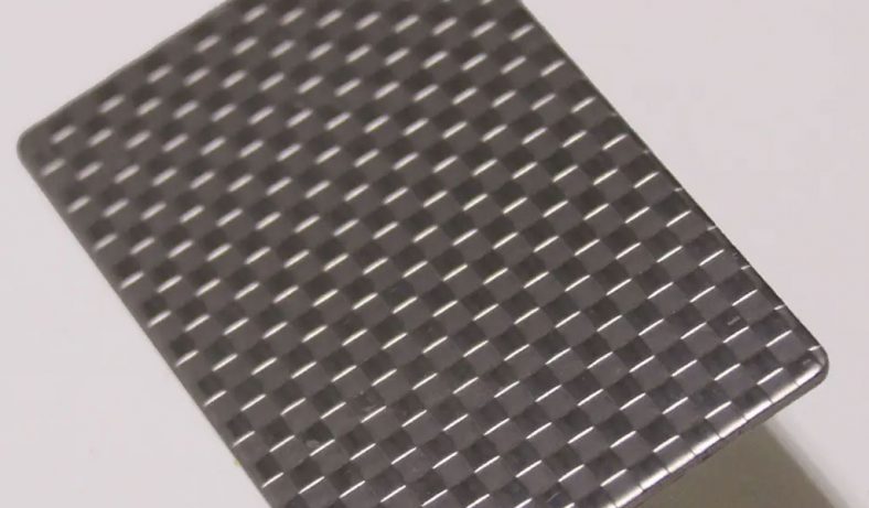
The surface morphology of etched sapphire is characterized using techniques like scanning electron microscopy (SEM) and atomic force microscopy (AFM). These methods reveal the development of faceted planes, such as trigonal cells or inclined sidewalls, which enhance light scattering in LEDs.
Patterned Sapphire Substrates (PSS) in LED Fabrication
Role of PSS in LED Performance
Patterned sapphire substrates are integral to modern GaN-based LEDs, addressing two primary challenges:
- Dislocation Reduction: PSS promotes ELOG, where GaN grows laterally over the patterned features, bending threading dislocations and reducing their propagation into the active quantum well region. This improves the internal quantum efficiency (IQE) by minimizing non-radiative recombination.
- Light Extraction Efficiency (LEE): The textured surface of PSS scatters light, reducing total internal reflection at the GaN-sapphire interface. This increases the escape cone for photons, enhancing the external quantum efficiency (EQE).
Studies have reported light output power enhancements of 17–71% for LEDs grown on PSS compared to planar substrates, depending on the pattern geometry and etching technique.
Common PSS Patterns
Several PSS patterns have been developed to optimize LED performance, each with distinct etching requirements:
- Semi-spherical PSS (r-PSS): Features dome-shaped patterns created by dry etching or self-assembled masks, later refined by wet etching to form faceted planes. These patterns offer moderate LEE enhancement (up to 30%).
- Conical PSS (CSPSS): Consists of cone-shaped features formed by dry etching followed by wet etching to expose r-planes. CSPSS reduces dislocation density more effectively than r-PSS, with LEE improvements of 40–50%.
- Six-facet PSS (A-PSS): Created by wet etching r-PSS to form hexagonal pyramids with (1-102) planes. A-PSS achieves high LEE (up to 67%) due to increased scattering surfaces.
- Truncated Triangle PSS: Features striped patterns with truncated tops, fabricated through wet etching in H₂SO₄:H₃PO₄ at 260–300°C. These patterns enhance light trapping for specific LED designs, such as flip-chip LEDs.
The choice of pattern depends on the LED application, with white-light LEDs favoring A-PSS for uniform phosphor distribution and blue LEDs benefiting from CSPSS for dislocation reduction.
Fabrication Process
The fabrication of PSS typically involves the following steps:
- Substrate Preparation: A c-plane sapphire wafer (2–8 inches) is cleaned to remove contaminants.
- Mask Deposition: A SiO₂ or SiNₓ layer (300–500 nm) is deposited via PECVD.
- Photolithography: A photoresist is patterned to define the desired features (e.g., 3 µm diameter circles with 3 µm spacing).
- Dry Etching (Optional): Inductively coupled plasma (ICP) etching with Cl₂ or BCl₃ gases creates initial patterns, such as cones or semi-spheres.
- Wet Etching: The substrate is immersed in a H₂SO₄:H₃PO₄ mixture (e.g., 3:1 at 230°C) for 5–30 minutes to refine the pattern and expose crystallographic planes.
- Mask Removal: The SiO₂ or SiNₓ mask is removed using buffered hydrofluoric acid (BHF).
- GaN Epitaxy: GaN layers are grown via MOCVD, with a low-temperature buffer layer to accommodate lattice mismatch.
The wet etching step is critical for achieving damage-free surfaces, as dry etching can introduce subsurface defects that degrade GaN quality.
Comparison of Wet and Dry Etching
Wet Etching Advantages
Wet etching offers several advantages over dry etching for PSS fabrication:
- Cost-Effectiveness: Wet etching requires simpler equipment (e.g., heated process tanks) compared to expensive ICP or reactive ion etching (RIE) systems.
- Damage-Free Surfaces: Wet etching produces smooth, defect-free surfaces, minimizing non-radiative recombination centers in GaN.
- Scalability: Wet etching can process multiple wafers simultaneously, enabling high-throughput production.
- Anisotropic Control: The crystallographic dependence of wet etching allows precise control over sidewall angles and facet formation.
Dry Etching Advantages
Dry etching, particularly ICP, is widely used for initial pattern formation due to:
- High Precision: Dry etching achieves uniform, densely packed patterns with submicron accuracy.
- Fast Etch Rates: ICP etching rates (up to 1000 Å/min) are suitable for deep patterns.
- Versatility: Dry etching can create complex geometries, such as vertical sidewalls, that are challenging with wet etching alone.
Trade-offs and Hybrid Approaches
Dry etching is slower (30–60 minutes per 2-inch wafer) and can damage the sapphire surface, necessitating a subsequent wet etching step to repair defects. Hybrid approaches, combining dry etching for pattern definition and wet etching for facet refinement, are common in industry. For example, a cone-shaped PSS may be dry-etched using BCl₃/Cl₂ plasma, followed by wet etching in 3:1 H₂SO₄:H₃PO₄ to form r-plane facets.
Table 1: Comparison of Wet and Dry Etching for Sapphire PSS Fabrication
| Parameter | Wet Etching | Dry Etching (ICP) |
|---|---|---|
| Etch Rate | 0.1–1 µm/min (at 260–300°C) | 100–1000 Å/min |
| Anisotropy | High (crystallographic dependence) | High (directional plasma) |
| Surface Damage | Minimal | Moderate to high |
| Cost | Low (simple equipment) | High (expensive plasma systems) |
| Throughput | High (batch processing) | Low (single-wafer processing) |
| Pattern Uniformity | Moderate (depends on mask quality) | High (submicron precision) |
| Typical Etchants/Gases | H₂SO₄:H₃PO₄ (1:1, 3:1, 6:1) | Cl₂, BCl₃, CH₂Cl₂ |
| Applications | Facet refinement, damage-free surfaces | Initial pattern definition, complex shapes |
Modeling and Simulation of Anisotropic Wet Etching
Continuum Level-Set Model
The complex topographies resulting from anisotropic wet etching are often modeled using continuum level-set methods, which track the evolution of the etch front over time. The level-set approach accounts for the orientation-dependent etch rates of sapphire, incorporating experimental data from spherical samples. The model uses a flexible interpolation method to describe local extrema in the etch rate distribution, ensuring accurate simulation of emerging crystal facets.
Wulff-Jaccodine Construction
The Wulff-Jaccodine (WJ) construction is a geometric method for predicting etch profiles based on the minimization of surface energy. By mapping the etch rate distribution onto a polar plot, the WJ method identifies stable facets (e.g., r-planes) that dominate the final pattern. Simulations using WJ agree well with experimental SEM images, confirming the formation of pyramidal or conical shapes.
Monte Carlo Simulations
Evolutionary kinetic Monte Carlo (KMC) methods simulate the atomic-scale dynamics of wet etching, modeling the layer-by-layer removal of Al atoms. KMC accounts for factors such as chemical bonding, surface diffusion, and etchant ion interactions, providing insights into the microscopic mechanisms of anisotropy. These simulations are particularly useful for optimizing etch conditions to achieve specific PSS geometries.
Impact of PSS on LED Performance
Internal Quantum Efficiency (IQE)
The IQE of GaN-based LEDs is limited by non-radiative recombination at threading dislocations. PSS reduces dislocation density by promoting ELOG, where GaN grows laterally over patterned features, bending dislocations away from the active region. Transmission electron microscopy (TEM) studies have shown that LEDs grown on PSS exhibit dislocation density as low as 10⁷ cm⁻², compared to 10⁹ cm⁻² on planar substrates. This results in IQE improvements of 20–30%.
Light Extraction Efficiency (LEE)
The LEE is enhanced by the scattering of light at the textured GaN-sapphire interface. Ray-tracing simulations indicate that PSS patterns like A-PSS increase the escape cone for photons, boosting LEE by 50–70%. The optimal pattern size (e.g., 2–3 µm diameter) and fill factor (60–80%) maximize scattering while maintaining GaN crystal quality.
Electrical Performance
LEDs on PSS exhibit improved electrical characteristics, including higher sub-threshold forward-bias voltage and lower reverse leakage current. These improvements stem from reduced defect density and uniform current spreading, facilitated by designs like strip-shaped SiO₂ distributed current blocking layers (DCBL).
Table 2: Impact of PSS Patterns on LED Performance
| PSS Pattern | Dislocation Density (cm⁻²) | LEE Enhancement (%) | IQE Improvement (%) | Light Output Power Increase (%) |
|---|---|---|---|---|
| Planar Substrate | 10⁹–10¹⁰ | 0 | 0 | 0 |
| Semi-spherical (r-PSS) | 10⁸–10⁹ | 20–30 | 10–15 | 17–30 |
| Conical (CSPSS) | 10⁷–10⁸ | 40–50 | 15–20 | 30–50 |
| Six-facet (A-PSS) | 10⁷–10⁸ | 50–70 | 20–25 | 67–71 |
| Truncated Triangle | 10⁸ | 30–40 | 10–15 | 20–35 |
Challenges and Future Directions
Challenges in Wet Etching
Despite its advantages, anisotropic wet etching faces several challenges:
- Mask Durability: High-temperature etching can degrade SiO₂ or SiNₓ masks, requiring thicker or alternative materials like Cr/Au.
- Etch Uniformity: Variations in etchant concentration or temperature across large wafers can lead to non-uniform patterns.
- Pattern Control: The complex anisotropy of sapphire makes it difficult to predict and control etch profiles for novel patterns.
- Environmental Concerns: The use of concentrated acids raises safety and disposal issues, necessitating greener etching solutions.
Emerging Techniques
Recent innovations aim to address these challenges:
- Laser-Induced Backside Wet Etching (LIBWE): Uses a carbon-based ink as a working solution to achieve precision etching via carbothermal reduction, offering smooth walls and high reproducibility.
- Self-Arranged Masks: Techniques like annealing Ni films or depositing Au nanodots create maskless patterns, reducing process complexity.
- Polishing Post-Etching: Methods developed by companies like Sinmat Inc. polish wet-etched patterns to mimic dry-etched dome shapes, enhancing LEE.
Future Research Directions
Future research should focus on:
- Alternative Etchants: Exploring less corrosive or environmentally friendly etchants, such as KOH melts or HF-based solutions, for sapphire etching.
- Advanced Modeling: Developing hybrid models combining level-set, KMC, and ray-tracing to optimize PSS designs for specific LED applications.
- Large-Scale Production: Scaling wet etching processes for 6–8-inch wafers to meet the demands of mass production.
- Integration with Novel LED Designs: Adapting PSS for emerging technologies like micro-LEDs, flip-chip LEDs, and UV LEDs.
Conclusion
Anisotropic wet etching of sapphire substrates is a cornerstone of modern LED manufacturing, enabling the production of high-efficiency GaN-based devices. By leveraging the crystallographic dependence of etch rates, wet etching creates patterned sapphire substrates that reduce dislocation density and enhance light extraction efficiency. The combination of H₂SO₄:H₃PO₄ etchants, high-temperature processing, and robust masking techniques allows precise control over PSS geometries, from semi-spherical to six-facet pyramids. While challenges like mask durability and etch uniformity persist, ongoing innovations in etching techniques and modeling promise to further improve LED performance. As the demand for energy-efficient lighting and advanced display technologies grows, anisotropic wet etching will remain a vital process in the evolution of LED technology.