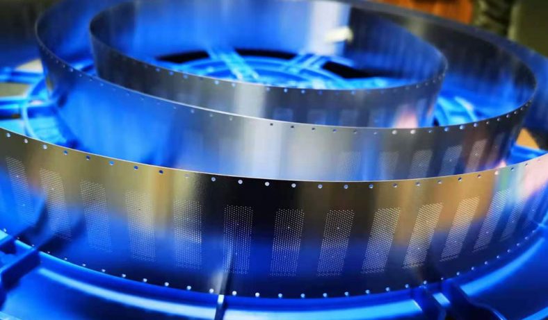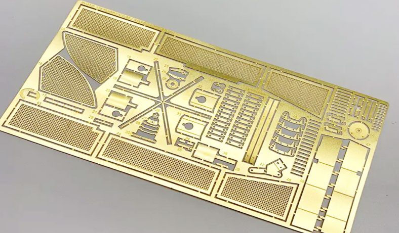
Electromagnetic interference (EMI) shielding is a critical aspect of modern electronics, ensuring that sensitive components are protected from unwanted electromagnetic radiation that could degrade performance or cause malfunctions. Aluminum-based materials, known for their high electrical conductivity, lightweight nature, and corrosion resistance, are widely used in EMI shielding applications. Among the various shielding structures, micro-hole arrays—patterns of small apertures etched into conductive materials—have gained significant attention due to their ability to balance electromagnetic shielding effectiveness (SE) with other functional requirements, such as ventilation, heat dissipation, and mechanical integrity. The manufacturing of these micro-hole arrays often relies on advanced etching techniques, which allow precise control over aperture size, shape, and distribution. These parameters directly influence the frequency-dependent impedance characteristics of the shielding material, which in turn affect its performance across a wide range of electromagnetic frequencies.
This article provides a comprehensive exploration of the etching manufacturing processes used to create aluminum-based micro-hole arrays for EMI shielding, with a detailed analysis of how these structures impact frequency impedance. It covers the principles of EMI shielding, the etching methods employed, the design considerations for micro-hole arrays, and the theoretical and experimental approaches to analyzing frequency impedance. The article also includes comparative tables to highlight key parameters and performance metrics, ensuring a thorough and scientific presentation suitable for researchers, engineers, and academics.
Fundamentals of Electromagnetic Interference Shielding
Principles of EMI Shielding
Electromagnetic interference shielding involves the use of conductive or magnetic materials to block or attenuate electromagnetic waves, preventing them from interfering with electronic devices. EMI shielding operates through three primary mechanisms: reflection, absorption, and multiple reflections. Reflection occurs when an electromagnetic wave encounters a material with a significant impedance mismatch, causing part of the wave to bounce back. Absorption involves the conversion of electromagnetic energy into heat as the wave interacts with electric or magnetic dipoles within the material. Multiple reflections occur within the material, particularly in structures with internal interfaces, such as micro-hole arrays, where waves are scattered and attenuated.
The shielding effectiveness (SE) of a material is quantified in decibels (dB) and is defined as the logarithmic ratio of the incident power to the transmitted power:
[ SE = 10 \log_{10} \left( \frac{P_{\text{incident}}}{P_{\text{transmitted}}} \right) ]
where ( P_{\text{incident}} ) is the power of the incident electromagnetic wave, and ( P_{\text{transmitted}} ) is the power of the wave that passes through the shield. SE is typically broken down into contributions from reflection (( SE_R )), absorption (( SE_A )), and multiple reflections (( SE_M )):
[ SE = SE_R + SE_A + SE_M ]
For metallic shields like aluminum, reflection is often the dominant mechanism due to their high electrical conductivity, which creates a significant impedance mismatch with free space (377 Ω). However, micro-hole arrays introduce additional complexity, as the apertures allow some electromagnetic waves to pass through, depending on their size relative to the wavelength of the incident radiation.
Role of Aluminum in EMI Shielding
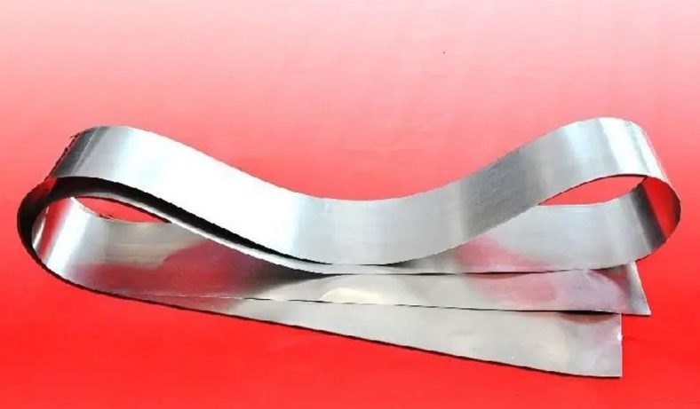
Aluminum is a preferred material for EMI shielding due to its favorable properties. With an electrical conductivity of approximately ( 3.5 \times 10^7 , \text{S/m} ), aluminum efficiently reflects electromagnetic waves, particularly in the radio frequency (RF) and microwave ranges (30 kHz to 20 GHz). Its low density (2.7 g/cm³) makes it ideal for applications where weight is a concern, such as in aerospace and automotive industries. Additionally, aluminum’s corrosion resistance and ease of processing enhance its suitability for shielding enclosures.
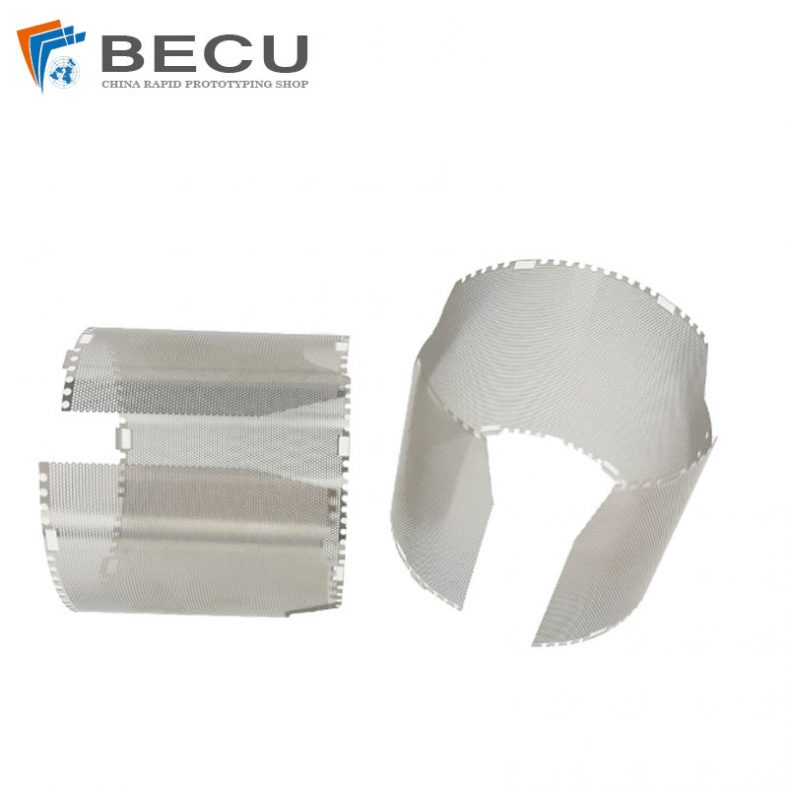
However, solid aluminum sheets can be impractical for applications requiring ventilation or heat dissipation, such as in electronic enclosures. Micro-hole arrays address this limitation by incorporating small apertures that allow airflow while maintaining acceptable shielding performance. The design of these arrays, including aperture size, shape, and spacing, significantly influences the shielding effectiveness and impedance characteristics, which are explored in later sections.
Etching Manufacturing Techniques for Micro-Hole Arrays
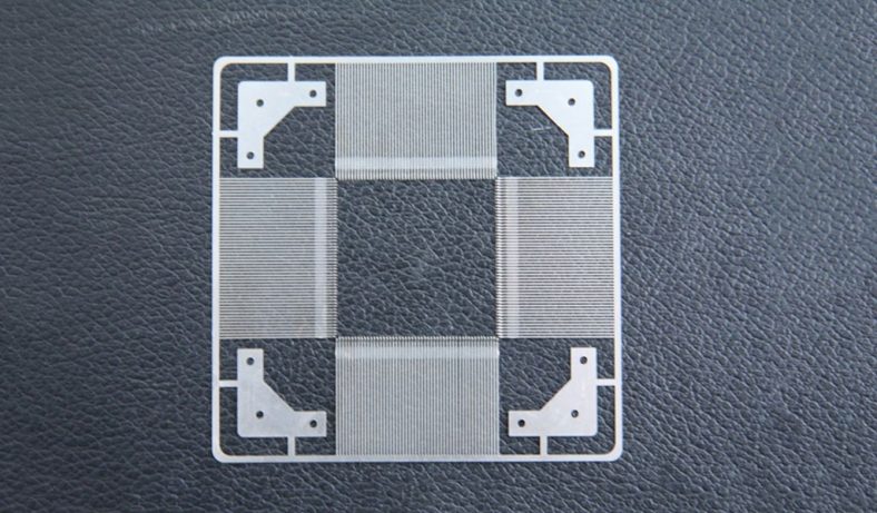
Overview of Etching Processes
Etching is a subtractive manufacturing process that removes material from a substrate to create precise patterns, such as micro-hole arrays. In the context of aluminum-based EMI shielding, etching techniques are chosen for their ability to produce high-precision apertures with controlled dimensions and minimal material deformation. The two primary etching methods for aluminum are chemical etching (wet etching) and laser etching, with additional techniques like electrochemical etching and plasma etching used in specialized applications.
Chemical Etching (Wet Etching)
Chemical etching involves immersing an aluminum substrate in a chemical solution that selectively removes material from unmasked areas. The process begins with the application of a photoresist mask, which defines the micro-hole pattern. The substrate is then exposed to an etchant, typically an acid or alkaline solution, such as hydrochloric acid (HCl) or sodium hydroxide (NaOH), which dissolves the exposed aluminum.
Advantages of Chemical Etching:
- Cost-effective for prototyping and small to medium production runs.
- Suitable for thin aluminum sheets (typically 0.05–0.5 mm).
- Capable of producing complex patterns with high resolution.
Disadvantages:
- Limited to thinner materials due to isotropic etching, which can cause undercutting.
- Slower processing times compared to laser etching.
- Environmental concerns due to chemical waste.
Laser Etching
Laser etching uses a focused laser beam to ablate material from the aluminum surface, creating precise micro-holes. Modern fiber lasers are particularly effective for aluminum, overcoming challenges associated with its high reflectivity. The process allows for rapid, high-precision patterning without the need for chemical solutions.
Advantages of Laser Etching:
- High precision and minimal thermal distortion.
- Suitable for thicker aluminum sheets (up to 0.25 inches).
- Fast processing times, ideal for high-volume production.
Disadvantages:
- Higher equipment costs compared to chemical etching.
- Potential for micro-burrs or heat-affected zones in thin materials.
Electrochemical Etching
Electrochemical etching involves applying an electric current to an aluminum substrate immersed in an electrolyte, causing controlled material removal. This method is less common but offers high precision for specific applications, such as micro-hole arrays with sub-micron features.
Advantages:
- High precision for small-scale features.
- Minimal mechanical stress on the substrate.
Disadvantages:
- Complex setup and slower processing times.
- Limited to specialized applications.
Plasma Etching
Plasma etching uses ionized gas to remove material from the aluminum surface. It is typically used for micro-scale features in semiconductor manufacturing but can be adapted for EMI shielding applications requiring ultra-fine apertures.
Advantages:
- Extremely high precision for micro-scale features.
- Uniform etching with minimal undercutting.
Disadvantages:
- Expensive equipment and complex process control.
- Limited to thin substrates and small-scale production.
Process Parameters and Optimization
The performance of micro-hole arrays in EMI shielding depends on the etching process parameters, including etchant concentration, temperature, exposure time, and laser power or pulse duration. For chemical etching, the etchant concentration and temperature must be carefully controlled to achieve uniform hole sizes and avoid over-etching. For laser etching, parameters such as laser wavelength, power, and scanning speed determine the hole quality and edge smoothness.
Table 1: Comparison of Etching Techniques for Aluminum Micro-Hole Arrays
| Parameter | Chemical Etching | Laser Etching | Electrochemical Etching | Plasma Etching |
|---|---|---|---|---|
| Material Thickness | 0.05–0.5 mm | 0.05–6.35 mm | 0.01–0.5 mm | 0.01–0.2 mm |
| Hole Size Range | 50 µm–1 mm | 10 µm–5 mm | 1 µm–500 µm | 0.1 µm–100 µm |
| Precision | Moderate | High | Very High | Extremely High |
| Processing Speed | Slow | Fast | Moderate | Slow |
| Cost | Low | High | Moderate | Very High |
| Environmental Impact | High (chemical waste) | Low | Moderate | Low |
| Applications | Prototyping, low-volume | High-volume, complex designs | Micro-scale features | Ultra-fine features |
Design of Micro-Hole Arrays for EMI Shielding
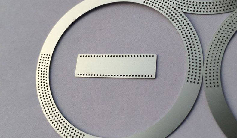
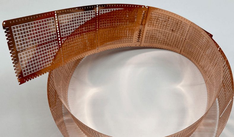
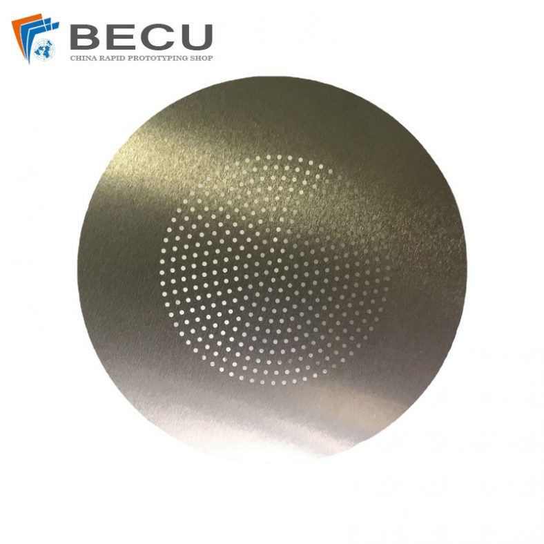
Aperture Size and Shape
The size and shape of micro-holes in aluminum arrays are critical determinants of EMI shielding performance. According to electromagnetic theory, the shielding effectiveness of an aperture is related to the wavelength (( \lambda )) of the incident radiation and the aperture’s largest dimension (( L )). A simplified expression for the shielding effectiveness of a single aperture is:
[ S(\text{dB}) = k \log_{10} \left( \frac{\lambda}{2L} \right) ]
where ( k ) is a constant (20–40, depending on the aperture shape), and ( L < \lambda/2 ). When ( L \geq \lambda/2 ), the shielding effectiveness approaches zero, as the aperture acts like a waveguide, allowing waves to pass through.
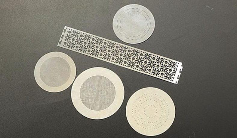
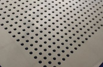
Common aperture shapes include circular, rectangular, and hexagonal patterns. Circular holes are preferred for their uniform stress distribution and ease of manufacturing, while hexagonal arrays (e.g., honeycomb structures) maximize open area for ventilation while maintaining high shielding effectiveness. The choice of shape affects the impedance characteristics, with circular holes providing more isotropic behavior compared to rectangular slots, which exhibit directional dependence.
Array Configuration and Spacing
The arrangement and spacing of micro-holes influence both shielding effectiveness and impedance. Closely spaced holes increase the open area percentage, improving ventilation but reducing shielding performance at higher frequencies. Conversely, wider spacing enhances shielding but may restrict airflow. A common design approach is to use a staggered or honeycomb pattern to optimize both parameters.
Table 2: Effect of Aperture Size and Spacing on Shielding Effectiveness
| Aperture Size (mm) | Spacing (mm) | Open Area (%) | SE at 1 GHz (dB) | SE at 10 GHz (dB) |
|---|---|---|---|---|
| 0.1 | 0.2 | 20 | 80 | 60 |
| 0.5 | 0.5 | 30 | 60 | 40 |
| 1.0 | 1.0 | 40 | 50 | 20 |
| 2.0 | 2.0 | 50 | 40 | 10 |
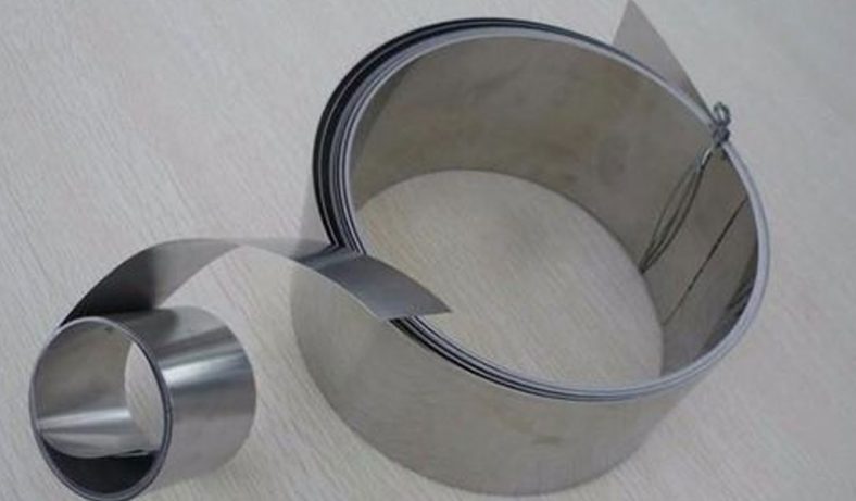
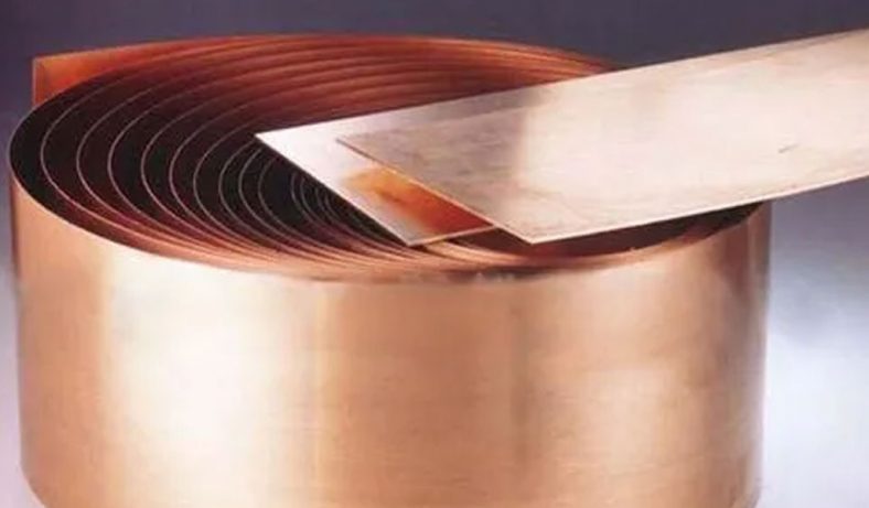
Material Thickness and Coating
The thickness of the aluminum substrate affects both the mechanical strength and the absorption component of shielding effectiveness. Thicker materials enhance absorption but may increase weight and cost. Thin aluminum foils (e.g., 16.3 µm) have been shown to provide high absorption-dominated shielding (e.g., 89.3 dB at 8–12 GHz), with reflection contributing less (15.4 dB) due to their high permittivity.
Coatings, such as zinc or aluminum bronze, can further enhance shielding performance by improving surface conductivity or corrosion resistance. For example, a 50 µm zinc coating on polyphenylene sulfide (PPS) increased SE significantly, suggesting similar benefits for aluminum-based arrays.
Frequency Impedance Analysis
Theoretical Framework
The impedance of a micro-hole array is a complex quantity that includes both resistive and reactive components, influenced by the material’s electrical properties and the geometry of the apertures. The impedance (( Z )) of a shielding material is given by:
[ Z = R + jX ]
where ( R ) is the resistance, ( X ) is the reactance, and ( j ) is the imaginary unit. For aluminum, the high conductivity results in low resistance, but the presence of micro-holes introduces inductive and capacitive effects that alter the reactance.
The impedance mismatch between the shield and free space is a key factor in reflection-dominated shielding. The reflection loss (( RL )) can be calculated as:
[ RL = 20 \log_{10} \left| \frac{Z_W + Z_M}{Z_W – Z_M} \right| ]
where ( Z_W ) is the wave impedance of free space (377 Ω), and ( Z_M ) is the impedance of the material. For micro-hole arrays, the effective impedance is reduced due to the apertures, which act as waveguides at higher frequencies, allowing partial transmission.
Frequency-Dependent Behavior
The impedance of micro-hole arrays varies with frequency due to the skin effect and the waveguide-like behavior of the apertures. At low frequencies (e.g., 30 kHz–1 MHz), the skin depth is large, and the entire thickness of the material contributes to conduction, resulting in low impedance. As frequency increases (e.g., 1–20 GHz), the skin depth decreases, and the apertures dominate the impedance characteristics.
Table 3: Impedance Characteristics Across Frequency Ranges
| Frequency Range | Skin Depth (µm) | Impedance (Ω) | Dominant Mechanism |
|---|---|---|---|
| 30 kHz–1 MHz | 100–1000 | 0.1–1 | Reflection |
| 1–600 MHz | 10–100 | 1–10 | Reflection/Absorption |
| 8–12 GHz (X-band) | 1–10 | 10–50 | Absorption/Multiple Reflections |
| 12–20 GHz | 0.5–1 | 50–100 | Waveguide Effects |
Experimental Analysis
Experimental studies often use a vector network analyzer (VNA) to measure the scattering parameters (S-parameters) of micro-hole arrays, which are then used to calculate SE and impedance. For example, the ASTM D4935-99 standard employs a coaxial waveguide setup to measure SE up to 1.5 GHz. The setup involves placing the sample between two coaxial flanges, with the VNA measuring the transmitted and reflected power.
Recent studies have shown that aluminum micro-hole arrays with aperture sizes of 0.1–1 mm provide SE values ranging from 40–80 dB in the 1–10 GHz range, with impedance values increasing with frequency due to the waveguide effect. The use of honeycomb structures, which consist of electrically connected tubes, has been shown to achieve up to 120 dB at 18 GHz, attributed to their high absorption and minimal transmission.
Advanced Manufacturing and Impedance Optimization
3D Printing and Hybrid Approaches
Recent advancements in additive manufacturing, such as magnetically assisted 3D printing, have enabled the creation of tailored micro-hole arrays with optimized impedance characteristics. By aligning conductive fillers (e.g., graphite microplatelets) during printing, researchers have achieved SE values up to 90 dB in the X-band (8–12 GHz), with a 200% increase in SE compared to non-aligned structures.
Impedance Matching Techniques
To minimize reflection and enhance absorption, impedance matching techniques are employed. These involve adjusting the array’s geometry or adding dielectric or magnetic coatings to reduce the impedance mismatch with free space. For example, stacking polymer composite layers with conductive fillers, such as carbon fiber or graphene, can optimize impedance matching and increase SE.
Applications and Future Directions
Applications in Electronics
Aluminum-based micro-hole arrays are used in a wide range of applications, including telecommunications, aerospace, and consumer electronics. In telecommunications, high-profile shielding with micro-hole arrays protects base stations from interference. In aerospace, lightweight arrays are critical for reducing weight while maintaining EMI protection.
Future Research
Future research should focus on developing sustainable etching processes, such as environmentally friendly etchants or laser-based methods with reduced energy consumption. Additionally, integrating smart materials, such as tunable metamaterials, could enable dynamic impedance control for adaptive shielding.
Conclusion
The etching manufacturing of aluminum-based micro-hole arrays for EMI shielding is a complex but highly effective process that balances shielding performance with functional requirements like ventilation and weight reduction. Chemical and laser etching are the dominant techniques, offering trade-offs in precision, cost, and scalability. The frequency-dependent impedance of these arrays, influenced by aperture size, shape, and material properties, plays a critical role in determining shielding effectiveness. Through careful design and optimization, micro-hole arrays can achieve high SE across a wide frequency range, making them indispensable in modern electronics. Continued advancements in manufacturing and impedance analysis will further enhance their performance and applicability.