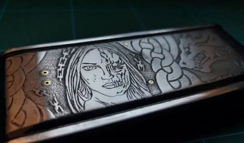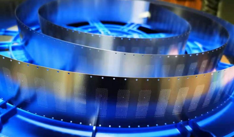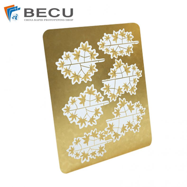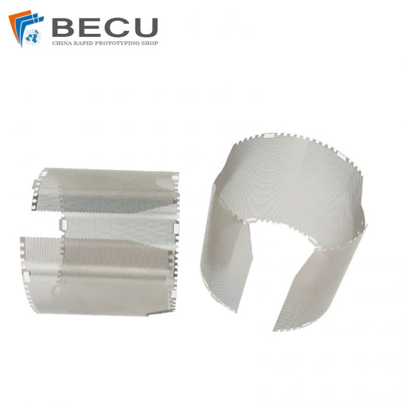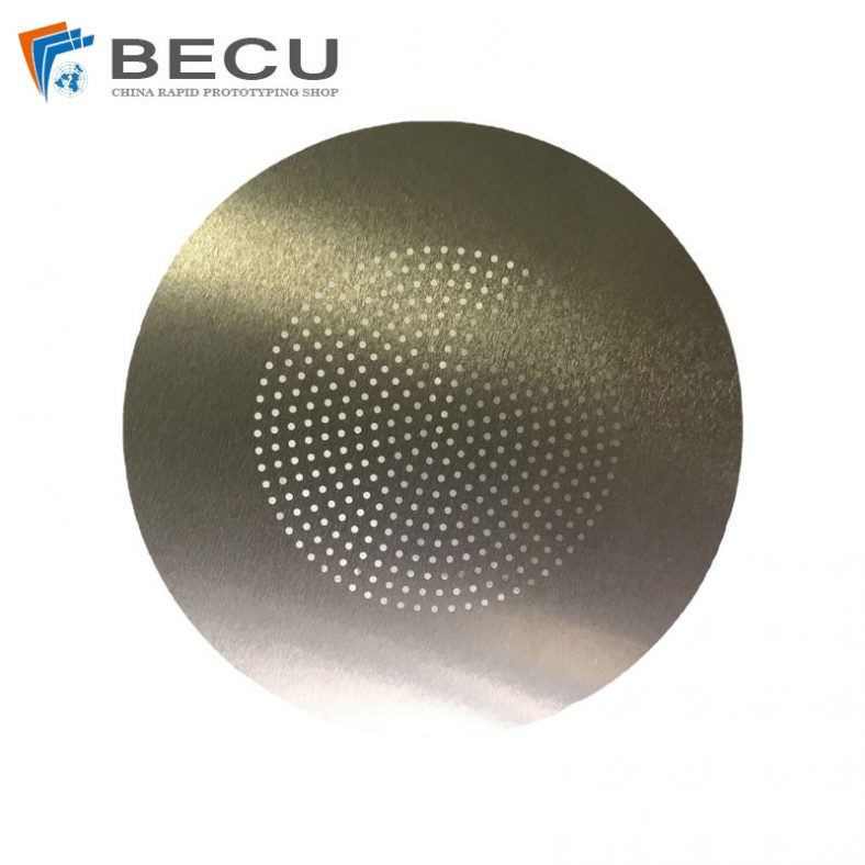
Chemical etching has long been a cornerstone in materials processing, allowing precise removal of material from metal surfaces through controlled chemical reactions. This technique finds applications across industries, from microelectronics and aerospace components to decorative arts and precision engineering. While etching can produce smooth finishes or intricate patterns, the behavior of the process—particularly whether it proceeds isotropically or anisotropically—profoundly influences the resulting surface morphology. Isotropic etching removes material uniformly in all directions, often leading to rounded profiles and increased surface roughness over time. In contrast, anisotropic etching exhibits direction-dependent rates, typically faster along certain crystallographic planes, yielding faceted structures, sharp edges, and controlled topography evolution.
The evolution of surface morphology during etching is not merely a byproduct but a critical factor determining functional properties such as wettability, adhesion, optical reflectance, and mechanical strength. For metals, chemical etching often involves acidic or alkaline solutions that dissolve the substrate via redox reactions, with morphology changes driven by factors like etchant composition, temperature, exposure time, and inherent material anisotropy. In polycrystalline metals, grain boundaries and orientations introduce local variations, while in single crystals, pronounced anisotropy can emerge. Understanding these dynamics enables tailored surfaces, from superhydrophobic textures to atomically flat planes.
This discussion explores the fundamentals of anisotropy in chemical etching, mechanisms governing morphology evolution, influencing parameters, and practical comparisons, drawing on established processes for metals like stainless steel, copper, aluminum, nickel, and titanium alloys.
Fundamentals of Isotropic and Anisotropic Etching
Etching processes are classified as isotropic or anisotropic based on directional preferences in material removal. Isotropic etching occurs when the reaction rate is limited by diffusion or uniform chemical attack, resulting in equal removal rates horizontally and vertically. This produces undercut profiles beneath masks and hemispherical or rounded features. Common in many wet chemical etches for metals, such as nitric acid-based solutions for stainless steel or hydrochloric acid for aluminum, isotropic behavior dominates when the etchant reacts non-selectively with the surface.
Anisotropic etching, however, shows preferential removal along specific directions, often tied to crystallographic orientations in crystalline materials. In metals, true crystallographic anisotropy is less pronounced than in semiconductors like silicon (where KOH etches {100} planes much faster than {111}), but it can manifest through grain-oriented attack, passivation layers, or catalyst-assisted processes. For instance, in metal-assisted chemical etching (MACE) of silicon-influenced metal systems or dealloying of alloys, directional porosity develops. In pure metals, anisotropy may arise from stressed regions or oxide formation differences.
A key distinction lies in profile shapes: isotropic etching yields bowed sidewalls and increased lateral undercut, while anisotropic produces straight, vertical walls or faceted pits. Surface roughness typically increases more rapidly in isotropic processes due to uniform dissolution amplifying initial irregularities.
| Aspect | Isotropic Etching | Anisotropic Etching |
|---|---|---|
| Directional Preference | Uniform in all directions | Preferential along specific planes/directions |
| Typical Profile | Rounded, undercut | Straight walls, faceted pits |
| Roughness Evolution | Steady increase from amplified defects | Selective smoothing or faceting |
| Common Etchants (Metals) | HNO3/HF mixtures, FeCl3 for general metals | Oriented acids, MACE with noble metals |
| Applications | Bulk removal, smoothing | Precise features, textured surfaces |
This table highlights practical differences observed in metal etching, where isotropic dominates conventional acid dips, and anisotropic emerges in specialized setups.
Mechanisms of Surface Morphology Evolution
Surface morphology evolves through interplay of dissolution kinetics, diffusion, and surface energy minimization. In early stages, etching attacks high-energy sites like defects, grain boundaries, or protrusions, initially increasing roughness. As exposure continues, competing effects—such as redeposition, passivation, or planarization—may reduce roughness.
For isotropic etching in metals, morphology often progresses from polished to pitted, then to roughened with craters or terraces. Ferric chloride etching of stainless steel, for example, dissolves chromium-rich areas preferentially at first, exposing iron-nickel regions and creating micro-pits that coalesce into larger features. Roughness (Ra) can rise from sub-micron to several microns over hours, depending on concentration.
Anisotropic mechanisms involve orientation-dependent activation energies. In alloys like Ni-Cu, electrochemical dealloying selectively removes copper, leaving porous nickel networks with ligament structures reflecting diffusion paths rather than strict crystallography. In titanium alloys, acidic etching can reveal alpha-beta phase differences, leading to stepped morphologies.
Stress-assisted etching further drives anisotropy: compressive stress accelerates dissolution at asperities, amplifying roughness in low-frequency modes while damping high-frequency ones. This explains why loaded metal surfaces develop specific wavenumber-dominant textures during etching.
Evolution stages typically include:
- Initiation: Pit formation at defects.
- Growth: Coalescence and deepening.
- Stabilization: Passivation or equilibrium roughness.
Temperature accelerates all stages, while additives (e.g., surfactants) can modulate by adsorbing preferentially on facets.
Parameters Influencing Anisotropy and Morphology
Etchant composition is paramount. Acidic etchants like sulfuric acid on nickel produce thorn-like structures with increasing time, boosting roughness from ~1 μm to >6 μm Ra, transitioning surfaces from hydrophilic to hydrophobic.
Time and temperature: Longer exposure deepens features; higher temperatures enhance anisotropy by overcoming activation barriers on slow planes.
Metal microstructure: Polycrystalline metals show intergranular attack, increasing roughness; single crystals may flatten via anisotropic dissolution.
Agitation and concentration gradients can induce macro-anisotropy by uneven etchant supply.
| Parameter | Effect on Isotropy/Anisotropy | Effect on Roughness Evolution |
|---|---|---|
| Etchant Concentration | Higher → faster, more isotropic | Increases peak roughness faster |
| Temperature | Higher → reduced anisotropy in some cases | Accelerates growth, may stabilize earlier |
| Exposure Time | Prolonged → shifts to equilibrium | Initial rise, then plateau or decrease |
| Metal Grain Size | Finer grains → more boundaries, isotropic | Higher initial roughness |
| Additives/Surfactants | Can induce faceting (anisotropic) | Smooths or textures selectively |
Comparisons from stainless steel etching with FeCl3 show roughness peaking at intermediate times before slight smoothing via over-etching.
Case Studies in Metal Etching
Stainless steel etching with ferric chloride illustrates typical isotropic behavior with morphology evolving from smooth to orange-peel texture, then pitted. Roughness increases with time up to a saturation point.
Nickel etching in sulfuric acid develops hierarchical structures: initial polishing, then micro-thorns, yielding superhydrophobic surfaces (contact angles >140°).
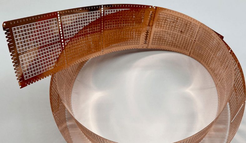
Copper and brass often use ferric chloride, producing uniform dissolution with moderate roughness suitable for printed circuit boards.
Titanium alloys, etched in HF-based mixtures, reveal phase-selective anisotropy, creating nano-porous surfaces for biomedical implants.
In advanced processes like MACE-inspired for metals, noble metal catalysts induce vertical pores, mimicking silicon anisotropy.
Comparison Tables for Common Metal Etchants
| Metal | Common Etchant | Behavior (Iso/Aniso) | Typical Roughness Change (Ra, μm) | Morphology Features |
|---|---|---|---|---|
| Stainless Steel | FeCl3 | Mostly isotropic | 0.5 → 5+ over hours | Pits, craters |
| Nickel | H2SO4 | Isotropic with texture | 1 → 6+ | Thorns, hierarchical |
| Aluminum | HCl/NaOH | Isotropic | Rapid increase | Uniform pitting |
| Copper | FeCl3 or CuCl2 | Isotropic | Moderate | Smooth to etched grains |
| Titanium | HF/HNO3 | Partial anisotropic | Variable, phase-dependent | Stepped, porous |
Another comparison for evolution over time (generic acidic etch):
| Time (min) | 5 | 30 | 60 | 120 |
|---|---|---|---|---|
| Roughness (Ra, μm) | Slight increase | Peak growth | Coalescence | Stabilization |
| Dominant Feature | Micro-pits | Craters | Terraces | Macro-texture |
These tables synthesize observations from industrial processes and studies, showing consistent trends.
Applications and Control Strategies
Controlled morphology from etching enhances adhesion (rough surfaces for coatings), reduces friction, or imparts hydrophobicity. In aerospace, etched titanium improves bond strength; in electronics, precise copper etching enables fine circuits.
To mitigate unwanted roughness, post-etch polishing or inhibitors are used. For desired anisotropy, oriented crystals or catalysts guide dissolution.
Conclusion
The interplay of anisotropy and surface morphology in chemical etching of metals offers remarkable control over final properties. While isotropic processes provide simplicity and uniformity, anisotropic variants enable sophisticated texturing. By tuning parameters, engineers can predict and harness evolution for optimal outcomes, making etching indispensable in modern manufacturing.