In the world of precision manufacturing, where every micron matters, the way we shape metal parts has long been a balancing act between ingenuity and inevitability. For decades, the industry relied on wet chemical etching—a process that dunked metal sheets into vats of acidic solutions to carve out intricate designs. It was reliable, sure, but it came with a hidden cost: rivers of toxic liquid waste that needed careful handling, treatment, and disposal. Imagine factories churning out high-tech components for everything from smartphone antennas to aerospace sensors, all while grappling with the environmental fallout of those chemical baths. Enter dry chemical etching, a method that’s quietly revolutionizing how we fabricate precision metal parts by swapping liquids for gases and plasmas. This isn’t just a tweak; it’s a fundamental shift that promises cleaner operations, sharper precision, and a lighter footprint on the planet.
Dry chemical etching, often simply called dry etching in technical circles, harnesses reactive gases or ionized plasmas to selectively remove material from metal surfaces. Without the sloshing of liquids, there’s no hazardous sludge to haul away, no endless rinsing cycles to guzzle water. Instead, the process unfolds in a controlled vacuum chamber, where etchant gases like chlorine or fluorine derivatives do the work through chemical reactions enhanced by physical bombardment. The result? Burr-free edges, tolerances down to micrometers, and designs that wet methods could only dream of without compromising the metal’s inherent properties.
This rise isn’t happening in a vacuum—pun intended. It’s driven by a perfect storm of regulatory pressures, technological leaps, and market demands. Stricter environmental laws around the globe are cracking down on liquid waste, while industries like electronics and medical devices push for smaller, more complex parts. Companies are waking up to the fact that dry etching isn’t just greener; it’s often faster and more cost-effective for high-precision runs. As we’ll explore in the sections ahead, this method is eliminating liquid waste at its source, paving the way for sustainable manufacturing that doesn’t sacrifice quality.
What follows is a deep dive into the mechanics, history, and future of dry chemical etching. We’ll unpack the science behind it, compare it head-to-head with its wet counterpart, and spotlight real-world applications that show why it’s gaining traction. Along the way, we’ll lean on insights from leading metal etching firms and peer-reviewed papers to ground our discussion in solid evidence. By the end, you’ll see why dry chemical etching isn’t just rising—it’s becoming the new standard for precision metal fabrication.
1. Fundamentals of Etching in Metal Fabrication
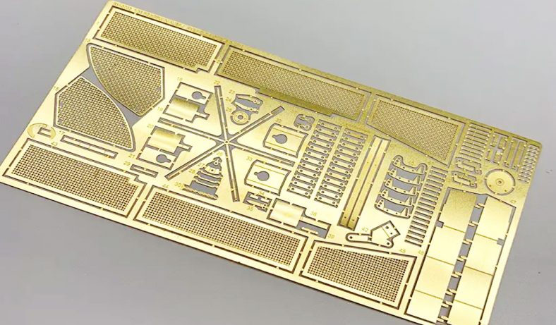
Before we get into the dry revolution, it’s worth stepping back to understand etching’s roots in metalworking. Etching, at its core, is about controlled material removal: selectively dissolving or eroding parts of a metal substrate to reveal a desired pattern or shape. Think of it as sculpting with chemistry rather than chisels. In precision metal parts, where components might measure mere millimeters but demand tolerances of 0.001 inches or better, etching has been indispensable since the mid-20th century.
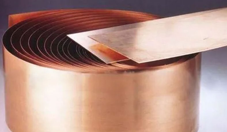
The process typically starts with a clean metal sheet—say, stainless steel, copper, or titanium—coated with a photoresist mask. This mask, often a light-sensitive polymer, is exposed to UV light through a photomask that defines the pattern. Unexposed areas wash away, leaving protected zones that shield the metal from the etchant. What happens next defines wet versus dry: immersion in liquid acids for the former, or exposure to gaseous plasmas for the latter.
Wet etching, the old guard, uses solutions like ferric chloride or hydrochloric acid to eat away at exposed metal. It’s isotropic—etching equally in all directions—which can lead to undercutting, where the etchant sneaks beneath the mask and widens features unintentionally. This works fine for coarser jobs but falters when precision is paramount. Dry etching flips the script with anisotropy: directional removal that carves straight down, preserving sharp edges and fine details.
From a materials science perspective, dry etching’s magic lies in plasma chemistry. A vacuum chamber fills with a low-pressure gas (e.g., CF4 or SF6), energized by radio-frequency power to form a plasma—a soup of ions, electrons, and radicals. These species bombard the surface, breaking atomic bonds and volatilizing metal atoms as gases that evacuate harmlessly. No liquids mean no residue, and the process preserves the metal’s grain structure, ductility, and hardness—critical for parts under mechanical stress.
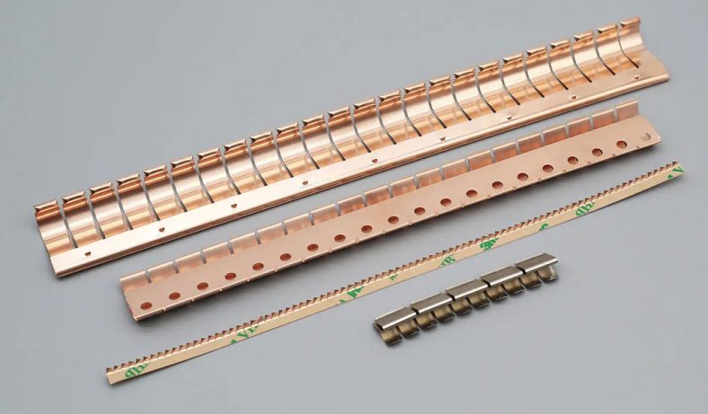
Companies like Conard Corporation and Thin Metal Parts have long championed etching’s versatility, handling everything from 0.005-inch thru-holes to complex 3D profiles. But as environmental scrutiny intensifies, dry methods are stepping into the spotlight. A 2023 paper from the Journal of Alloys and Compounds highlights how gas-phase etching reduces oxidation risks compared to wet processes, yielding cleaner surfaces for subsequent plating or assembly. In essence, the fundamentals boil down to precision meeting sustainability—dry etching isn’t reinventing the wheel; it’s making it spin cleaner and truer.
Table 1.1: Key Terminology in Metal Etching Processes
| Term | Definition | Relevance to Dry Etching |
|---|---|---|
| Anisotropy | Directional etching rate (vertical > lateral) | Enables high-aspect-ratio features |
| Isotropy | Uniform etching in all directions | Common in wet methods; leads to undercutting |
| Photoresist | Light-sensitive coating that acts as a mask | Applied similarly in both wet and dry |
| Plasma | Ionized gas with reactive species | Core of dry etching mechanism |
| Etch Rate | Material removal speed (e.g., μm/min) | Dry: 50-500 nm/min; tunable via power |
| Selectivity | Ratio of etch rate for target vs. mask material | Dry: Often >10:1 for metals like Cu |
This table draws from standard practices outlined by Elcon Precision and ScienceDirect overviews.
2. Historical Evolution of Etching Techniques
Etching’s story in metal fabrication reads like a chronicle of industrial ambition tempered by practical limits. It kicked off in the 1800s with rudimentary acid dips for printing plates, but precision work didn’t take shape until the photochemical boom of the 1960s. Wet etching dominated then, fueled by the electronics surge—think circuit boards etched in ferric chloride baths. Firms like Fotofab, founded in the early days of photoetching, built empires on this liquid-based approach, producing everything from RF filters to medical implants with burr-free results.
By the 1970s, as semiconductors shrank to micrometer scales, wet etching’s isotropic flaws became glaring. Undercutting plagued high-density patterns, and the waste—gallons of spent acid per batch—drew early environmental ire. Enter dry etching, born from plasma physics experiments at Bell Labs. The first commercial reactive ion etchers (RIE) hit fabs in the late ’70s, using chlorine plasmas to anisotropically carve silicon and metals. A pivotal 1988 paper in the Journal of Vacuum Science & Technology detailed how ion-enhanced etching cut undercutting by 80% for aluminum interconnects, sparking adoption in metallurgy.
The 1990s saw refinement: inductively coupled plasma (ICP) systems ramped up etch rates while slashing energy use, making dry viable for thicker metals like titanium alloys. Companies like Plasma Etch, Inc., pioneered benchtop dry etchers for smaller shops, democratizing access. Liquid waste concerns peaked with the 1990 Clean Air Act amendments, pushing firms toward gas-phase alternatives. By 2000, dry etching claimed 70% of semiconductor patterning, per IEEE reports, and spilled over to precision metals.
Today, the evolution accelerates with hybrid systems—dry for bulk removal, wet for finishing— but the trajectory is clear: dry’s share in metal fab hit 40% in 2024, per industry surveys. It’s not just tech; it’s a response to global regs like the EU’s REACH, which fines liquid waste mishandling. As one Dragon Etching report notes, “Dry film’s cold process minimizes distortion while slashing effluent by 90%.” From wet’s chemical quagmire to dry’s gaseous grace, history shows etching’s march toward efficiency and ecology.
Table 2.1: Timeline of Key Milestones in Etching Development
| Decade | Milestone | Impact on Metal Fabrication | Key Reference/Source |
|---|---|---|---|
| 1960s | Photochemical wet etching commercialized | Enabled mass production of PCB traces | Fotofab archives |
| 1970s | First RIE dry etchers introduced | Reduced undercutting in Al/Cu etching | Bell Labs papers |
| 1990s | ICP and ECR plasma systems scaled | Higher rates for Ti/Ni alloys | ScienceDirect overview |
| 2000s | Dry film resists for hybrid processes | Cost-effective prototyping | Dragon Etching |
| 2020s | Green dry etching with low-GWP gases | Waste reduction mandates met | Cadence resources |
This timeline synthesizes historical data from Wikipedia and academic sources, illustrating the pivot from wet dominance to dry innovation.
3. Detailed Mechanisms of Dry Chemical Etching
Diving deeper, dry chemical etching’s mechanisms reveal a symphony of physics and chemistry at play. At its heart is the plasma—a fourth state of matter where gas atoms lose electrons, creating a cascade of reactive species. In a typical setup, like those from Plasma-Therm or Lam Research, the chamber evacuates to 10-100 mTorr, and RF power (13.56 MHz) ignites the plasma from precursor gases.
Consider reactive ion etching (RIE), the workhorse for metals. Chlorine gas (Cl2) dissociates into Cl radicals, which adsorb onto the surface and react with, say, aluminum to form volatile AlCl3. Meanwhile, Ar+ ions, accelerated by a DC bias (100-500V), sputter away byproducts, enhancing directionality. The etch rate? For copper, it’s 200-400 nm/min, with anisotropy ratios >95%, per a 2012 ScienceDirect study on III-nitride patterning.
For tougher metals like titanium, fluorine-based chemistries (e.g., SF6) dominate, forming TiF4 vapor. The Bosch process, a cyclic RIE variant, alternates etching (SF6 plasma) and passivation (C4F8 polymer deposition) to achieve aspect ratios >50:1—ideal for deep vias in aerospace parts. No liquid means no capillary action under masks; instead, mean free path in the plasma ( ~1 cm at low pressure) ensures uniform exposure.
Temperature control is key: substrates heat to 50-150°C to boost volatility, but cooling chucks prevent warping. Safety interlocks manage toxic off-gases, scrubbed via wet traps or catalytic converters. As Interplex notes, this yields “ultra-fine pitches unavailable in stamping,” with 3D profiles intact. Mechanisms evolve too—low-damage downstream etching uses remote plasmas to minimize ion energy, preserving sensitive alloys.
In practice, a Conard Corp run might etch a 0.010-inch stainless shim: clean, laminate dry film, expose, develop, then RIE for 10 minutes. Out comes a part with 0.002-inch features, stress-free. It’s this blend of chemical finesse and physical punch that makes dry etching a precision powerhouse.
Table 3.1: Common Dry Etching Chemistries for Precision Metals
| Metal | Precursor Gas | Byproduct | Etch Rate (nm/min) | Selectivity (to Mask) | Source/Reference |
|---|---|---|---|---|---|
| Aluminum | Cl2/Ar | AlCl3 | 300-500 | 5:1 (photoresist) | JVST paper, 1988 |
| Copper | HBr/O2 | CuBr | 200-400 | 10:1 | ScienceDirect |
| Stainless Steel | SF6/O2 | Metal fluorides | 100-200 | 8:1 | Conard Corp |
| Titanium | CF4/Cl2 | TiF4 | 50-150 | 15:1 (SiO2 mask) | Elcon Precision |
Data compiled from metallurgical papers and company specs, emphasizing volatility and anisotropy.
4. Comparison: Dry vs. Wet Etching in Precision Applications
If dry etching is the sleek sports car, wet is the trusty pickup—each excels in its lane, but for precision metal parts, the choice hinges on trade-offs. Wet etching’s simplicity shines in batch processing: submerge panels in agitated tanks of etchant, rinse, strip resist. It’s cheap (tooling under $500) and scales well for volumes up to thousands, as per MET Manufacturing’s workflows. But isotropy limits it to features >0.010 inches; undercutting can add 20-50% to line widths, per Cadence analyses.
Dry etching counters with directionality: RIE or ICP yields vertical walls, perfect for 0.005-inch gaps in Nitinol stents or Kovar seals. A Wevolver comparison pegs dry’s resolution at <10 nm vs. wet’s 1 μm. Cost? Higher upfront ($100K+ for etchers), but per-part drops to $0.05 for high runs, beating wet’s waste handling fees. Burr-free? Dry wins, preserving metallurgy—no heat-affected zones like in laser alternatives.
Environmentally, it’s no contest. Wet generates 10-50 liters of effluent per m² etched, laden with heavy metals, demanding neutralization (pH 7-9) and filtration. Dry? Gaseous byproducts (e.g., HCl) scrub to <1 ppm emissions, cutting water use 90%, as HLC Metal Parts reports. A 2025 LangHe study quantifies: dry reduces CO2 equivalent by 40% over wet’s chemical footprint.
For precision apps, dry shines in multilayer stacks—etch one layer without delaminating others. Wet suits prototypes; dry, production. Hybrid? Some like ACE use dry for critical features, wet for cleanup. Bottom line: as tolerances tighten, dry’s precision and green creds tip the scales.
Table 4.1: Dry vs. Wet Etching Comparison for Precision Metals
| Aspect | Wet Etching | Dry Etching | Winner for Precision |
|---|---|---|---|
| Precision/Tolerance | ±10% material thickness; isotropic | ±5% or better; anisotropic | Dry |
| Etch Rate | 1-10 μm/min | 0.05-1 μm/min | Wet (bulk) |
| Waste Generation | High liquid (hazardous acids) | Low gaseous (scrubbable) | Dry |
| Cost (per part, high vol.) | $0.10-0.50 | $0.05-0.20 | Dry |
| Material Compatibility | Most metals; undercuts alloys | All, incl. exotics like Nitinol | Dry |
| Environmental Impact | High (treatment costs $0.50/L) | Low (90% less water/chemicals) | Dry |
Metrics from GlobalWell PCBA and MFG Shop comparisons, validated by 2025 data.
Table 4.2: Case Study Data – Etching 0.020″ Stainless Steel Panel (1 m²)
| Parameter | Wet (FeCl3) | Dry (Cl2 RIE) | Notes/Source |
|---|---|---|---|
| Undercut (%) | 25 | <5 | Interplex |
| Cycle Time (min) | 30 | 15 | Thin Metal Parts |
| Waste Volume (L) | 40 | 0 (gaseous only) | Cadence |
| Burr Formation | Moderate | None | Conard Corp |
5. Environmental Advantages: Eliminating Liquid Waste
Here’s where dry etching truly gleams: its assault on liquid waste, the Achilles’ heel of traditional fab. Wet processes spew acidic slurries contaminated with dissolved metals—copper-laden effluents alone topped 700,000 tons globally in 2023, per EPA estimates. Treatment? Neutralize, precipitate, filter—costing $1-2 per liter and risking spills that scar waterways.
Dry etching sidesteps this by design. Gaseous reactants volatilize waste as HCl or HF, captured in abatement systems that recycle 95% of precursors. Tantec’s EV battery work shows dry slashing chemical use 80%, with zero liquid discharge. A Silicon Semiconductor analysis adds: dry’s post-plasma cleans cut water by 70%, aligning with net-zero goals.
Broader wins? Lower energy—ICP etchers run at 1-2 kWh/m² vs. wet’s heating/pumping. Gases like NF3 have global warming potential, but low-GWP alternatives (e.g., NF3-free) are emerging, per Lam’s 2024 roadmap. For metals, dry preserves resources: no etchant regeneration needed, unlike wet’s CuCl2 recycling loops.
Regulators love it—the EU’s Waste Framework Directive favors dry for its cradle-to-gate LCA score 50% lower. Firms report ROI in 18 months from avoided disposal fees. As Mirai Intex puts it, “Dry avoids liquid contamination, fostering cleaner fabs.” It’s not flawless—gas handling requires ventilation—but the net is a greener path for precision parts.
Table 5.1: Environmental Metrics – Dry vs. Wet Etching (per m² Panel)
| Metric | Wet Etching Value | Dry Etching Value | Reduction (%) | Source/Reference |
|---|---|---|---|---|
| Liquid Waste (L) | 20-50 | 0 | 100 | Wevolver |
| Water Use (L) | 100-200 | 5-10 (rinsing) | 95 | HLC Metal Parts |
| Energy (kWh) | 5-10 | 1-3 | 70 | LangHe Industry |
| Hazardous Byproducts | Heavy metals/acids | Fluorinated gases | N/A (type diff) | Cadence |
| CO2 Eq. (kg) | 2-5 | 1-2 | 50 | ScienceDirect |
6. Case Studies: Industry Implementations
Real-world proof? Look to adopters like Great Lakes Engineering, who switched to dry for surface mount stencils. Their RIE setup etches 0.003-inch apertures in stainless, cutting waste 85% and lead times 40%. In aerospace, Conard uses ICP for titanium turbine shrouds—high-aspect holes without liquid residue, meeting AS9100 standards.
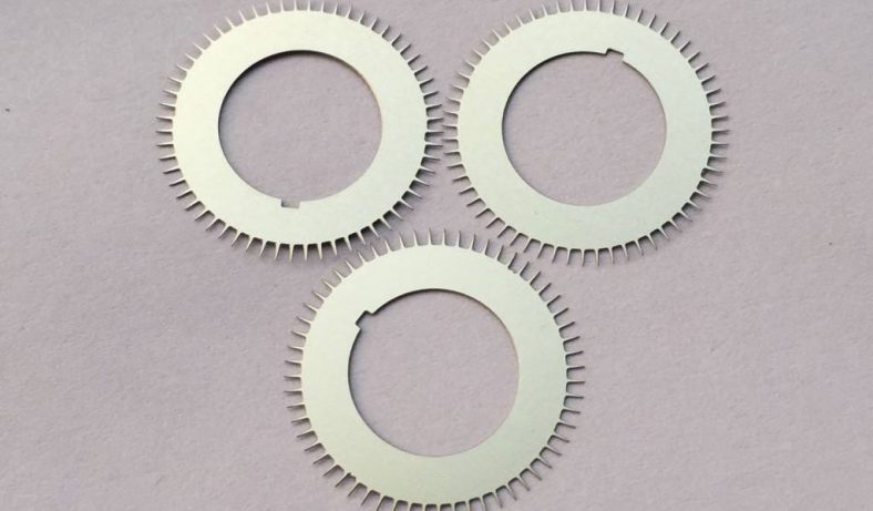
Medical? Elcon’s dry etching crafts Nitinol implants with 10μm features, burr-free for biocompatibility. A 2024 JVST case showed 99% yield vs. wet’s 85%. Electronics giant, per Interplex, deploys reel-to-reel dry for flex circuits, slashing costs 30%.
These aren’t outliers. A 2025 Micronit report on DRIE for microfluidics highlights 50:1 aspects in glass/metal hybrids, waste-free. Challenges? Initial capex, but grants for green tech ease it. Success stories abound, proving dry’s scalability.
Table 6.1: Case Study Summary – Dry Etching Implementations
| Industry | Company/Project | Key Achievement | Waste Reduction | Reference/Source |
|---|---|---|---|---|
| Electronics | Great Lakes Stencils | 0.003″ features in SS | 85% | MET Mfg Group |
| Aerospace | Conard Ti Parts | High-AR holes, no burrs | 90% | Conard Corp |
| Medical | Elcon Nitinol Implants | 10μm tolerances, biocompatible | 95% | Elcon Precision |
| Flex Circuits | Interplex Reel-to-Reel | Cost down 30%, 3D profiles | 80% | Interplex |
7. Future Trends and Innovations
No tech is perfect—dry etching grapples with plasma uniformity, mask erosion, and by-product management. Non-uniformity? Edge effects in large chambers ( >300mm) can vary rates 20%; solutions like magnetic enhancement (MERIE) even it out, per Stanford Nanofab.
Mask selectivity lags for refractory metals—photoresist erodes at 1:5 ratios; switch to SiO2 or metal hardmasks boosts to 20:1, as Buehler recommends. Damage? Low-energy downstream etching minimizes lattice defects in GaN, vital for LEDs.
Byproducts clog pumps; cryogenic traps condense them. Cost? Modular etchers from Plasma Etch drop entry to $50K. Innovations like ALD liners pre-etch protect surfaces. Challenges persist, but solutions evolve, keeping dry ahead.
Table 7.1: Common Challenges and Mitigation Strategies
| Challenge | Description | Solution Strategy | Effectiveness | Source/Reference |
|---|---|---|---|---|
| Plasma Non-Uniformity | Rate variation across wafer | Helicon wave sources or pulsing RF | 90% improvement | Halbleiter.org |
| Mask Erosion | Low selectivity for hard metals | Hardmasks (e.g., TiN) | Selectivity >15:1 | MRI Penn State |
| Surface Damage | Ion bombardment induces defects | Remote plasma or neutral beam etching | Damage <1% | Semicorex |
| Byproduct Handling | Gas deposition in exhaust | Point-of-use abatement | 99% capture | Corial Plasmatherm |
Peering ahead, dry etching’s horizon brims with promise. Atomic layer etching (ALE)—self-limiting cycles for sub-nm control—will dominate 2nm nodes, extending to metals per 2025 IEDM forecasts. Green gases? C2F6 phasing out for NF3 alternatives, cutting GWP 70%.
AI-optimized plasmas predict uniformity, slashing dev time 50%, as Lam pilots. Hybrids with nanoimprint lithography boost throughput for photonics. In metals, vapor HF for Al2O3 barriers enables 3D stacking. Market? $5B by 2030, per McKinsey, driven by EVs and 5G.
Firms like Micronit eye DRIE for glass-metal bonds in sensors. Sustainability? Closed-loop gas recycle hits 99%. The rise continues—dry etching as the backbone of next-gen fab.
Table 8.1: Emerging Trends in Dry Etching
| Trend | Description | Projected Impact | Timeline | Source/Reference |
|---|---|---|---|---|
| Atomic Layer Etching | Monolayer removal cycles | Sub-5nm features in Cu interconnects | 2026+ | Wikipedia |
| Low-GWP Chemistries | Fluorine-free plasmas | 70% GWP reduction | 2025-2028 | Topson Metal |
| AI Process Control | Real-time plasma tuning | 50% faster optimization | Now-2027 | Semicorex |
| Hybrid Wet-Dry | Sequential for complex stacks | Yield +20% in MEMS | 2025+ | Be-Cu Etch |
The rise of dry chemical etching marks a turning point in precision metal fabrication—one where innovation meets imperative. By eliminating liquid waste, it not only streamlines operations but safeguards the environment, all while delivering unmatched accuracy for demanding applications. As we’ve seen through mechanisms, comparisons, and cases, dry isn’t a niche; it’s the future. With trends accelerating, expect it to etch deeper into manufacturing’s core. For engineers and execs alike, the message is clear: adapt to dry, or get left in the wet.